Animation Tutorial: Electric Sparks: Difference between revisions
| Line 24: | Line 24: | ||
===Rate of Travel=== | ===Rate of Travel=== | ||
''(note: it is recommended to work on manage each layer as it's own layer group, and the base/streak boundaries should belong to their respective groups) | |||
[[File:Mister minations - tutorials - sparks - distance traveled.png|left|Determining how fast the spark is moving]] | [[File:Mister minations - tutorials - sparks - distance traveled.png|left|Determining how fast the spark is moving]] | ||
Revision as of 21:13, 19 November 2022
(insert introduction here)
Overview
(explain what an electrical spark is)
Components of an Electrical Spark
Base
Trail
Glow
Modeling
Boundaries and Direction
(note: it's highly recommended to place the components discussed here in their own layer group)

The first thing to do is to determine how big the resulting electrical spark should be, specifically as a result of two factors.
- Length: how long the spark can travel before it fizzles out
- Width: how many trails are produced by the base
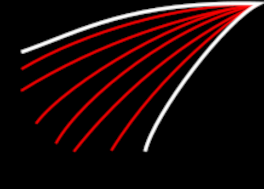
The components of the spark are thereby restricted to the space within the resulting boundary, represented by the white lines.
Next, the spark requires a direction. As the sparks travel, the resulting trail should follow a given path; deviating from the path causes jitter, which isn't pleasant to look at. For the sake of consistency, the red lines represent potential paths the primary and auxiliary trails can take. While it's a good idea to plan out specific paths for the trails beforehand, it's more than acceptable to plot out a number of equally-spaced lines and work from there.
That said, there should be a limit on the number of trails present. Remember: a spark is a streak of light. If too many trails are drawn, the result will be less a beam of light and more a block of solid color. For this reason, if paths are planned before hand, only a small number (around 3) of paths should act as primary trails, with each primary trail accompanied by a similarly small number of auxiliary trails
As always, the boundary and direction depend on context. However, it's important to know that a spark is fast. For example, at 15 frames per second, a spark only needs between 5 and 10 frames; anything less is to fast to register, and there can't be so many frames that the spark no longer looks like a streak of light. Therefore, size is also dependent on the number of frames involved. If a spark is too big and too many frames are needed, try shrinking the boundaries and try again. Conversely, if the spark is so small that the minimum frame count isn't met, a bigger boundary is needed.
Rate of Travel
(note: it is recommended to work on manage each layer as it's own layer group, and the base/streak boundaries should belong to their respective groups)

In general, the life cycle of an electrical spark can be divided into three phases: 1. Initialization: When a spark first appears, it's a single cone of light at the starting location. This cone of light will very quickly grow until it hits the next stage. This stage only contains around 2 frames. 2. Midpoint: Almost immediately after appearing, the base begins fizzling out. As it fizzles out, some of the light, no longer connected to the base, continues trailing outwards, following a given path. This phase is primarily a transition between phases 1 and 2, and only encompasses a single frame. 3. Fade Away: A spark is hot. As it travels, it gets increasingly cool until it's about the same temperature as the air around it, at which point it ceases to exist. In addition, as it cools, the trails of light move with increasing difficulty through the air, deaccelerating and shrinking until there's not enough heat left to keep moving.
Regarding point 3, not all trails fizzle out at the same time. The primary trails, owing to their increased length, will last until the final frame of animation. Conversely, any auxiliary trail, by definition, both begins smaller and fades out quicker, often several frames before the associated primary trail.
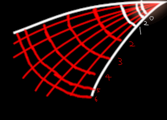
In the image to the left, items related to the base are white, and items related to the trails are drawn in red.
The numbers next to the boundaries represent what frames the boundaries relate to, with frame 2 appearing twice.
In general, as the base grows, the white lines should be equidistant. As the base fades away, either use one of the previously given boundaries, or draw a new boundary somewhat closer to the starting point. As stated before, the number of frames needed for the base should be minimized as much as possible.
In contrast, the distance between successive red boundaries should increasingly shrink. In general, deacceleration seems mostly occur near the end of the animation; the first few frames start out fairly equidistantly spaced, but the last few frames are closer together. By the end, the final pinpricks of light will teeter just next to the overall boundary.